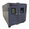
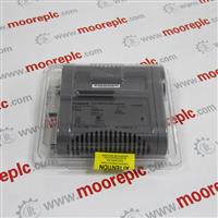
Module breakage tester Structure and principle:
It is one of the methods for checking the quality of electronic module soldering on-line. It is a system for testing the solder joints of electronic modules in the manufacturing environment. It replaces the traditional needle bed with a probe, and has 4 probes that can be moved at high speed on the XY mechanism. The needle is used to manually place the measuring unit into the testing machine, and the probe of the flying probe tester contacts the test pad and the via hole to test the welding effect of the components in the measuring unit. The test probe is connected to the driver and sensor through a multiplex system to test the components on the unit under test. When a component is being tested, other components on the unit are electrically shielded by the probe to prevent reading interference. , flying needle structure.
Module breakage tester Features:
1. Quickly locate and effectively measure pipeline anti-corrosion layer failure
2. The electromagnetic detection equipment for locating and measuring pipeline corrosion is gradually combined with the GIS system and the GPS system currently on the market to provide an accurate record of the relative relationship between pipeline condition, position and time for later drawing analysis. This is PCM+ One of the main features.
3, PCM+ preventive maintenance of the pipeline, extend the life of the pipeline, and find erosion at an early stage.
4. The PCM+ system includes a portable transmitter and a handheld receiver. The transmitter is connected to the CPS site to apply a special near DC signal to the pipe. The receiver can identify this special signal to locate the position and depth of the pipe within a range of 30 kilometers.
5. Once the pipeline is positioned, the technician can plot the leakage current along the pipeline, showing the magnitude and direction of the signal current, and quickly determining the damage of the coating.
6. After determining the damaged section of the pipeline, the A-shaped frame can be used to further determine the damage location and depth within 1 meter.
7. PCM+ has automatic signal attenuation, advanced current direction, and powerful functions for grounding compensation. It can even overlap with other metal structures, and there are electrical interference or pipelines in dense pipeline areas for accurate and easy positioning and mapping. Simultaneous measurements of PCM current and voltage gradients are provided. PCM current and voltage gradients are measured in real time.
8. The operator does not need to complete the “current span”. Without manual calculation, it is possible to determine the CP current propagating along the pipeline that usually needs to be directly connected to measure.
9. The mapping information of PCM+ in any mode is also stored and displayed on the receiver. The recorded mapping information can be transmitted to a PC or an optional PDA using Bluetooth, and displayed in a graphical format for quick analysis.
More product information sources:
**** />


